9.9.1: Skills Integration Challenge-Switched Ethernet
Markhamah Tri Utami
12 615 056
Tujuan Praktikum :
1. Mahasiswa dapat mengetahui cara menghitung IP
2. Mahasiswa dapat menetukan subnetting
3. Mahasiswa dapat melakukan uji koneksi
Pendahuluan
Ethernet switch merupakan sebuah network switch yang mentransmisikan data pada Ethernet standard rates. Ethernet merupakan sebuah kumpulan dari tool-tool jaringan komputer yang disatukan dengan satu set standar tertentu. Network switch merupakan istilah lainnya untuk sebuah perangkat yang menghubungkan bagian-bagian berbeda pada sebuah jaringan komputer bersama-sama.
Sebuah Ethernet switch harus mampu mentransmisikan data pada tingkatan tertentu untuk memastikan komputer dan semua perangkat yang terhubung dapat berfungsi dengan baik dan merupakan pusat kontrol lalu lintas (traffic control center) pada jaringan LAN (Local Area Network).
Langkah PraktikumTopology Diagram

Addressing Table

Background:
You have been asked to repair some problems in the network model related to the Ethernet LAN connected to R2-Central.
Task 1: IP Subnet planning
You have been given an IP address block of 192.168.111.0 /24. You must provide for the three existing networks.
Subnet Assignments Are:
- 1st subnet, existing student LAN, up to 100 hosts; (Fa0/0 on R2-Central)
- 2rd subnet, existing ISP LAN, up to 5 hosts; (already configured)
- 3rd subnet, existing WAN, point-to-point link; (already configured)
Interface IP addresses:
- The server, R1-ISP, and R2-Central's serial interface have already been configured.
- For R2-Central's Fa0/0 interface, use the highest usable address on the existing student LAN subnet.
- For hosts 1A and 1B, use the first 2 IP addresses (two lowest usable addresses) on the existing student LAN subnet.
- For Hosts 1A and 1B, the DNS server is 192.168.111.133 /29.
- The next hop router (to which the default route should point), R1-ISP, has an IP address of 192.168.111.138 /30.
Task 2: Repair problems with the Ethernet switched LAN.
- PC 1B has a wireless card and cannot be connected to the switch; add the Fast Ethernet Interface card PT-HOST-NM-1CFE to PC 1B.
- Connect this newly installed Fast Ethernet NIC to the Fa0/2 interface on the switch.
- Connect PC 1A to the Fa0/1 interface on the switch.
- Connect the Fa0/24 interface on the switch to the R2-Central Fa0/0 interface.
Apparently the Ethernet speed and duplex settings for the R2-Central Fa0/0 interface, the S1-Central switch interfaces (Fa0/1, Fa0/2, and Fa0/24), and the PC 1A interfaces are incorrect. Set all Ethernet interfaces to auto negotiate speed and duplex (which will achieve Full Duplex, 100 Mbps operation, if both ends of the link can support it). For all devices, make sure the power is on to the device and to the interfaces (make sure the Ethernet interfaces are not shut down). Add IP addresses to the router Fa0/0 interface and to the two PCs-- highest usable subnet address assigned to the gateway; two lowest usable addresses to the PCs. The static route on the R2-Central should be a default static route which points via R1-ISP's serial interface IP address. These procedures were explained in the Chapter 5 and 6 Skills Integration Challenges.
Task 3: Test the Network.
Use ping, trace, web traffic, and the Inspect tool to trace packet flow in simulation mode, with HTTP, DNS, TCP, UDP, ICMP, and ARP viewable, to test your understanding of how the network is operating.
Reflection:
The two Layer 2 (and Layer 1 technologies) in this model are a serial connection (between the routers) and the Ethernet LANs (for the ISP server and with S1-Central switch). Compare and contrast the serial connection with Ethernet. In a future course you will learn much more about switched Ethernet technologies.
Setelah membaca instruksi diatas yang pertama adalah menyiapkan IP address dan subnest mask untuk jumlah host 100. Caranya adalah dengan melakukan subnetting langsung saja kita melakukan subnetting untuk kasus ini :
· R2 – Central
Analisa
IP yang saya gunakan berada di kelas C dengan subnest mask /25 yang berarti 11111111.11111111.11111111.10000000 (255.255.255.128).
Setelah itu untuk menentukan host yaitu dengan cara menggunakan angka yang lebih dari 100 rumusnya (2n-2), n adalah jumlah 0 yang ada di oktet terakhir. 128 – 2 = 126. Jumlah host sudah dapat sekarang adalah waktunya memasukkan IP dan subnest mask kedalam router
Konfigurasi router
R2-Central>enable
R2-Central#config t
Enter configuration commands, one per line. End with CNTL/Z.
R2-Central(config)#interface fa0/0
R2-Central(config-if)#ip address 192.168.111.126 255.255.255.128
R2-Central(config-if)#no shutdown
R2-Central(config-if)#
%LINK-5-CHANGED: Interface FastEthernet0/0, changed state to up
%LINEPROTO-5-UPDOWN: Line protocol on Interface FastEthernet0/0, changed state to up
R2-Central(config-if)#end
R2-Central#
%SYS-5-CONFIG_I: Configured from console by console
R2-Central#
Setelah konfigurasi router selesai selanjutnya adalah melakukan konfigurasi switch
· S1 – Central
S1-Central > enable
S1-Central # configurasi terminal
S1-Central (config)# interface fa0/1
S1-Central (config-if)# description Connection to host computer 1A
S1-Central (config)# interface fa0/2
S1-Central (config-if)# description Connection to host computer 1B
S1-Central (config)# interface fa0/3
S1-Central (config-if)# description Connection to R2-Central
S1-Central (config-if)# end
S1-Central copy run start
Destination filename [startup-config]?
Building configuration...
[OK]
S1-Central #
Konfigurasi semua sudah dilakukan seteleh melakukan pengaturan pada ethernet speed dan duplex pada R2-Central Fa0/0 interface, the S1-Central switch interfaces (Fa0/1, Fa0/2, and Fa0/24), dan PC 1A dan PC 1B

Lalu menentukan Next hop pada R2-Central

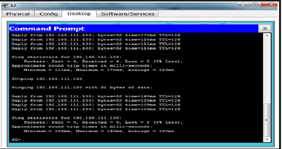
Hasil Praktikum
ping ke PC